September 2005
5
M9999-083005
MIC2588/MIC2594
Micrel
AC Electrical Characteristics
(5)
Symbol
Parameter
Condition
Min
Typ
Max Units
t
FLT
Built-in Overcurrent Nuisance Trip
400
祍
Time Delay
(6)
(Figure 1)
t
OCSENSE
Overcurrent Sense to GATE Low
V
SENSE
V
EE
= 100mV
3.5
祍
(Figure 2)
t
OVPHL
OV to GATE Low
(6)
(Figure 3)
1
祍
t
OVPLH
OV to GATE High
(6)
(Figure 3)
1
祍
t
UVPHL
UV to GATE Low
(6)
(Figure 4)
1
祍
t
UVPLH
UV to GATE High
(6)
(Figure 4)
1
祍
t
PGL(1)
DRAIN High to PWRGD Output Low
(6)
R
PULLUP
= 100k? C
LOAD
on PWRGD = 50pF
1
祍
(-1 Version parts only)
t
PGL(2)
DRAIN Low to /PWRGD Output Low
(6)
R
PULLUP
= 100k? C
LOAD
on /PWRGD = 50pF
1
祍
(-2 Version parts only)
t
PGH(1)
DRAIN Low to PWRGD Output High
(6)
R
PULLUP
= 100k? C
LOAD
on PWRGD = 50pF
2
祍
(-1 Version parts only)
t
PGH(2)
DRAIN High to /PWRGD Output High
(6)
R
PULLUP
= 100k? C
LOAD
on /PWRGD = 50pF
2
祍
(-2 Version parts only)
Notes:
5. Specication for packaged product only.
6. Not 100% production tested. Parameters are guaranteed by design.
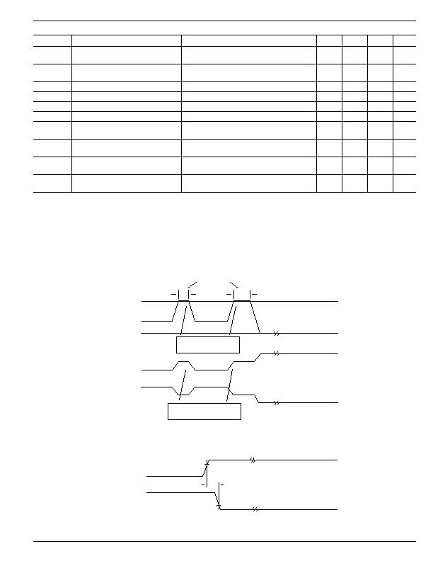
Timing Diagrams
I
LIMIT
I
LOAD
0A
V
DRAIN
V
GATE
(V
EE
+10V)
t < t
FLT
t ?t
FLT
(at V
EE
)
(at V
EE
)
(at V
EE
)
OVERCURRENT
EVENT
Output OFF
(at V
DD
)
Load current is regulated
at I
LIMIT
= 50mV/R
SENSE
Reduction in V
DRAIN
to support
I
LIMIT
= 50mV/R
SENSE
Figure 1. Overcurrent Response
V
SENSE
- V
EE
100mV
1V
t
OCSENSE
V
GATE
Figure 2. SENSE to GATE LOW Timing Response
发布紧急采购,3分钟左右您将得到回复。
相关PDF资料
MIC2595R-2BM TR
IC CTRLR HOT SWAP NEG HV 14-SOIC
MIC280-7BM6 TR
IC SUPERVISOR THERMAL SOT23-6
MIC2800-GFSYML TR
IC REG TRPL BUCK/LINEAR 16MLF
MIC281-7BM6 TR
IC SUPERVISOR THERMAL SOT23-6
MIC2810-1JGMYML TR
IC REG TRPL BUCK/LINEAR 16MLF
MIC284-2BMM TR
IC SUPERVISOR THERM 2ZONE 8-MSOP
MIC3385-1.5YHL TR
IC REG DL BCK/LINEAR SYNC 14-MLF
MIC384-1YMM
IC SUPERVISR THERM LOC/REM 8MSOP
相关代理商/技术参数
MIC2594-2YM
功能描述:热插拔功率分布 Negative Voltage Hot-Swap Controller - Lead Free
RoHS:否 制造商:Texas Instruments 产品:Controllers & Switches 电流限制: 电源电压-最大:7 V 电源电压-最小:- 0.3 V 工作温度范围: 功率耗散: 安装风格:SMD/SMT 封装 / 箱体:MSOP-8 封装:Tube
MIC2594-2YM TR
功能描述:热插拔功率分布 Negative Voltage Hot-Swap Controller - Lead Free
RoHS:否 制造商:Texas Instruments 产品:Controllers & Switches 电流限制: 电源电压-最大:7 V 电源电压-最小:- 0.3 V 工作温度范围: 功率耗散: 安装风格:SMD/SMT 封装 / 箱体:MSOP-8 封装:Tube
MIC2594-2YM-TR
功能描述:Hot Swap Controller 1 Channel -48V 8-SOIC 制造商:microchip technology 系列:- 包装:剪切带(CT) 零件状态:停产 类型:热交换控制器 通道数:1 内部开关:无 应用:-48V 特性:故障超时,闭锁故障 可编程特性:限流,压摆率,UVLO 电压 - 电源:-80 V ~ -19 V 电流 - 输出(最大值):- 工作温度:-40°C ~ 85°C 电流 - 电源:3mA 安装类型:表面贴装 封装/外壳:8-SOIC(0.154",3.90mm 宽) 供应商器件封装:8-SOIC 功能引脚:DRAIN,OFF,ON,/PWRGD 标准包装:1
MIC2595-1BM
功能描述:IC CTRLR HOT SWAP NEG HV 14-SOIC RoHS:否 类别:集成电路 (IC) >> PMIC - 热交换 系列:- 产品培训模块:Obsolescence Mitigation Program 标准包装:100 系列:- 类型:热插拔开关 应用:通用 内部开关:是 电流限制:可调 电源电压:9 V ~ 13.2 V 工作温度:-40°C ~ 150°C 安装类型:表面贴装 封装/外壳:10-WFDFN 裸露焊盘 供应商设备封装:10-TDFN-EP(3x3) 包装:管件
MIC2595-1BM TR
功能描述:IC CTRLR HOT SWAP NEG HV 14-SOIC RoHS:否 类别:集成电路 (IC) >> PMIC - 热交换 系列:- 产品培训模块:Obsolescence Mitigation Program 标准包装:100 系列:- 类型:热插拔开关 应用:通用 内部开关:是 电流限制:可调 电源电压:9 V ~ 13.2 V 工作温度:-40°C ~ 150°C 安装类型:表面贴装 封装/外壳:10-WFDFN 裸露焊盘 供应商设备封装:10-TDFN-EP(3x3) 包装:管件
MIC2595-1YM
功能描述:热插拔功率分布 Negative Voltage Hot-Swap Controller - Lead Free
RoHS:否 制造商:Texas Instruments 产品:Controllers & Switches 电流限制: 电源电压-最大:7 V 电源电压-最小:- 0.3 V 工作温度范围: 功率耗散: 安装风格:SMD/SMT 封装 / 箱体:MSOP-8 封装:Tube
MIC2595-1YM TR
功能描述:热插拔功率分布 Negative Voltage Hot-Swap Controller - Lead Free
RoHS:否 制造商:Texas Instruments 产品:Controllers & Switches 电流限制: 电源电压-最大:7 V 电源电压-最小:- 0.3 V 工作温度范围: 功率耗散: 安装风格:SMD/SMT 封装 / 箱体:MSOP-8 封装:Tube
MIC2595-1YM-TR
功能描述:Hot Swap Controller, Sequencer 1 Channel -48V 14-SOIC 制造商:microchip technology 系列:- 包装:剪切带(CT) 零件状态:停产 类型:热交换控制器,序列发生器 通道数:1 内部开关:无 应用:-48V 特性:闭锁故障 可编程特性:限流,故障超时,UVLO 电压 - 电源:-80 V ~ -19 V 电流 - 输出(最大值):- 工作温度:-40°C ~ 85°C 电流 - 电源:4mA 安装类型:表面贴装 封装/外壳:14-SOIC(0.154",3.90mm 宽) 供应商器件封装:14-SOIC 功能引脚:CFILTER,CNLD,DRAIN,PGTIMER,OFF,ON,PWRGD1,PWRGD2,PWRGD3 标准包装:1